
Wellhead installation is one of most fascinating topics and it is very difficult to visualize how this operation is performed. However, if you see this video, it will make the learning process so easy. This video demonstrate how to a stack wellhead from the beginning to the end of the process. Furthermore, we also add full video transcript which may help some learners to let more understanding.
There may be several strings of pipe in any given well. The number of the strings is determined by the number of zones being drilled through. These can include freshwater, saltwater and potential productions zones. Depicted here are 4 production or ‘pay zones’. Each zone would be cased off or isolated until it is to be produced.
On land, a majority of wells begin with digging a cellar, which can be from 3 to 15 feet in depth. The primary purpose of a cellar is to align the Christmas tree at relative ground-level. Having the Christmas tree at relative ground level allows for easier access to the valves, chokes and other equipment. The first string of pipe to be used in a well is called the conductor pipe or drive pipe. To being, a large diameter hole is drilled to a specified depth, generally relatively shallow, such as 1 or 200 feet. The pipe is driven into the ground to a specified depth or to the point of refusal. In most cases, an adaptor flange or a drilling flange is welded to the conductor pipe as a means to connect a diverter system or blowout preventer system.
Upon completion of the surface hole, the surface pipe is run to a specified depth to isolate any freshwater, saltwater, oil or gas zones within that depth range. The surface pipe is run and cemented in place back to the surface. A cement plug is left in the surface pipe, so that a diverter system or a BOP system may be disconnected or nippled down safely.
After the diverter or BOP system has been nippled down, the surface pipe is drained. Then the adapter flange or drilling flange is cut off. The final cut-off height is determined by adding the height of each piece of wellhead equipment, plus the stand-off distance between each piece of equipment and the rig gasket height. Then the depth of the slip on socket in the bottom of the casing head housing. If a base plate is used, its height must also be considered. The sum of these heights is then deducted from the cellar depth to determine the final cut-off height, for both the conductor pipe and surface casing.
When the final cut on the conductor and surface pipe is completed, the casing head housing is prepared for installation. The casing head housing is welded in place on the surface casing. The pieces welded on the inside diameter and the outside diameter, then tested to assure there are no leak paths in the wells. This test checks the wells, but does not test the integrity of the casing head housing. The base plate which is slightly larger than the conductor pipe, may be tack welded to the conductor pipe, if desired. The base plate serves as a means to transfer weight from the casing head housing back onto the conductor pipe. When the casing head housing has been successfully welded and tested, the BOP system is installed or nippled up and preparations are made to drill out for the intermediate string of casing. To test the BOP system, the test plug is made up from the drilling string and lowered through the BOP system, until properly located in the casing head bowl. Pressure is applied from above the plug and the BOP system is tested.
Upon completion of the BOP tests, the wear bushing running tool is made up on the drill string and the wear bushing installed on the running tool. The wear bushing is then lowered through the BOP system until located in the casing head bowl. The wear bushing is locked in place, either by lockdown pins in the casing head housing flange or by lockdown pins located in a lockdown flange. The running tool is then removed and the drilling operation can resume.
After the hole has been drilled for the intermediate string, the casing is run in the hole and cemented in place. The intermediate string is cemented to a predetermined depth to ensure a good cement bond is obtained between the surface casing and the intermediate casing. A cement plug is left in the intermediate casing, just as it was in the surface casing. The casing is then suspended from the elevators at the rig floor, and the casing hanger is installed either through the BOP system or underneath the BOP system.
In this example the casing hanger will be installed underneath the BOP system. To begin, the BOP system is nippled down and picked up to a height approximately 3 feet. The casing hanger is then installed. Holes are cut in the casing to allow the drilling fluids to drain out of the casing riser. When the casing has drained, a rough cut is made and the balance of the casing riser is removed. The BOP system is removed. The casing spool with a crossover seal is installed. The BOP system is nippled up and preparation is made to drill out for the production casing string.
To test the BOP system the test plug is made up on the drill string and lowered through the BOP system, until properly located in the casing spool bowl. Pressure is applied from above the plug and the BOP system is tested. Upon completion of the BOP tests, the wear bushing running tool is made up on the drill string and the wear bushing installed on the running tool. The wear bushing is then lowered through the BOP system until located in the casing spool bowl. The wear bushing is locked in place either by lockdown pins and the casing spool flange or by lockdown pins located in a lockdown flange. The running tool is then removed and the drilling operation can resume.
The production casing string is generally run to the total depth of the well and is the casing string in which the production packer is installed. When the hole is drilled and the production casing is run and cemented in place, the casing hanger is installed. The casing riser is drained. A rough cut is made and the BOP system removed. The final cut is made to the production casing in preparation for installation of the tubing spool. The tubing spool with a crossover seal is installed in the same manner as the casing spool. After the tubing spool has been installed, the seals and connection are tested and the BOP system is nippled up.
Preparations are now made to run production tubing in the hole. Production tubing is considered any pipe string 4 inches in diameter or less, though sometimes larger sizes of pipe are used. When the plug has been drilled out and a cleanout trip completed, the perforating gun is run in the hole and the casing is perforated or shot. The downhole packer assembly is run and installed in the production casing. A packer is in essence a CO assembly that isolates the reservoir from all strings of pipe, except the production tubing. The production tubing is run with a bottom hole assembly to seal inside the packer. After the tubing is spaced out and proper weight set on the packer, the tubing hanger is installed at the tubing on the rig floor, then lowered into the bowl of the tubing spool. The BOP system is nippled down and preparations are made to install the production Christmas tree.
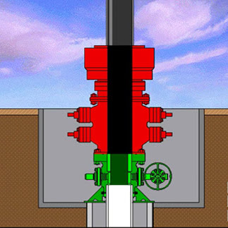
The production Christmas tree is made up of a seal flange which is often called the tubing head adapter, a series of gate valves, a T or cross, rig valves or side valves, and a choke. The Christmas tree is the group of equipment that controls the flow of the well. Each Christmas tree has one or more surface safety valves that will shutdown the well in an emergency, and prevent damage to the equipment downstream. To install the Christmas tree, determine the direction the Christmas tree should be installed, pick it up, level it and lower it over the extended neck of the well drill tubing hanger. The Christmas tree is nippled up to the tubing spool, and the connections and seals are tested. The well is now ready for production testing.
source: http://www.drillingformulas.com/well-head-installation-vdo/
source: http://www.drillingformulas.com/well-head-installation-vdo/